13 May SDX V
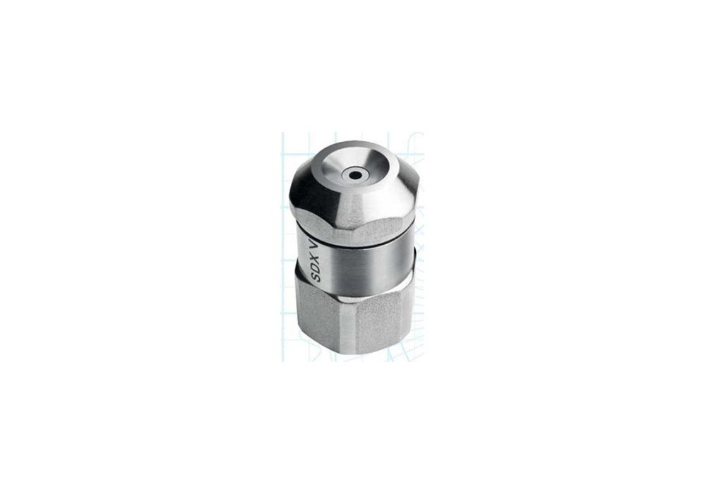
SDX V Spray Drying Nozzle 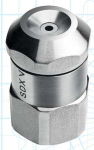
Delavan Spray Drying Nozzles – Taking Our Technical Leadership One Step Further
FEATURES AND BENEFITS
- Wear benefits are positively retained during assembly.
- Compatible with current SDX range.
- New internal design reduces pressure loss through the nozzle.
- Smaller and lighter compact design which is more durable, easy to clean and can be rapidly stripped down and reassembled.
- No wrenches or tools are required to install the nozzle.
- Minimal friction due to nozzle design permitting 10-20% lower operating pressure than conventional slotted distributor nozzle for equivalent atomization quality.
- Extended pump life due to lower operating pressure.
SPRAY CHARACTERISTICS
- The nozzle produces a hollow cone spray pattern with uniform particle size distribution even at low operating pressure.
- Reduction in fine particles is possible due to lower pressure requirements.
- Flow rats are certified to be within +/-5% of rated capacity at 69 Bar.G. and within +/-5% of rated spray angle when tested with water.
- Unique, patented single inlet spiral swirl chamber offers increased nozzle life, improved uniformity, density or solubility.
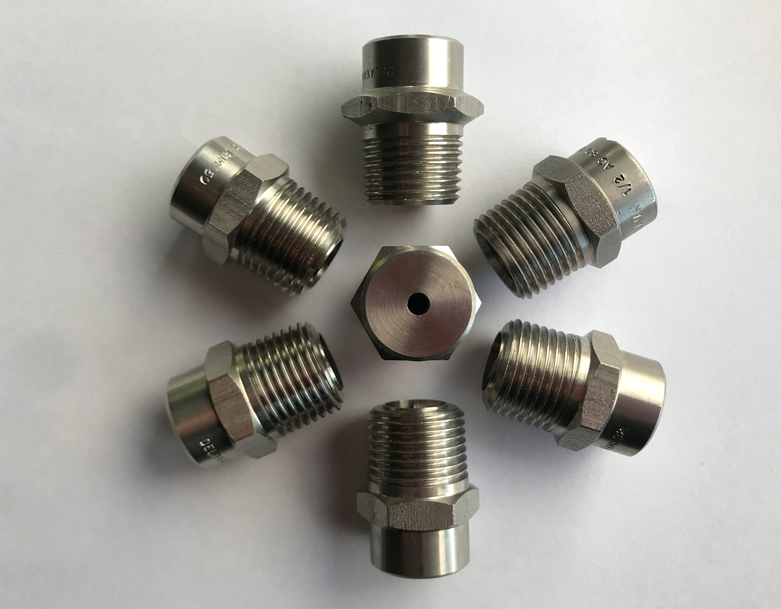
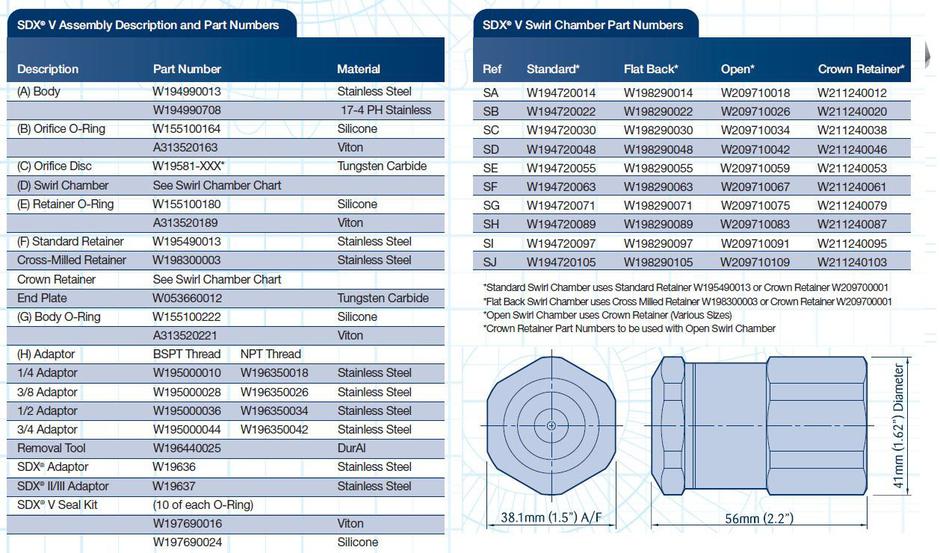
CONSTRUCTION AND MATERIALS
- 5 piece construction with ‘O’ ring seals.
- Nozzle body and adaptors are available in 316 Stainless Steel.
- Wear parts are in Tungsten Carbide.
- O-rings are in Silicone or Viton.
- O-ring seals allow assembly and disassembly without tools.
ORDER EXAMPLE
Please indicate all component parts and materials when ordering.
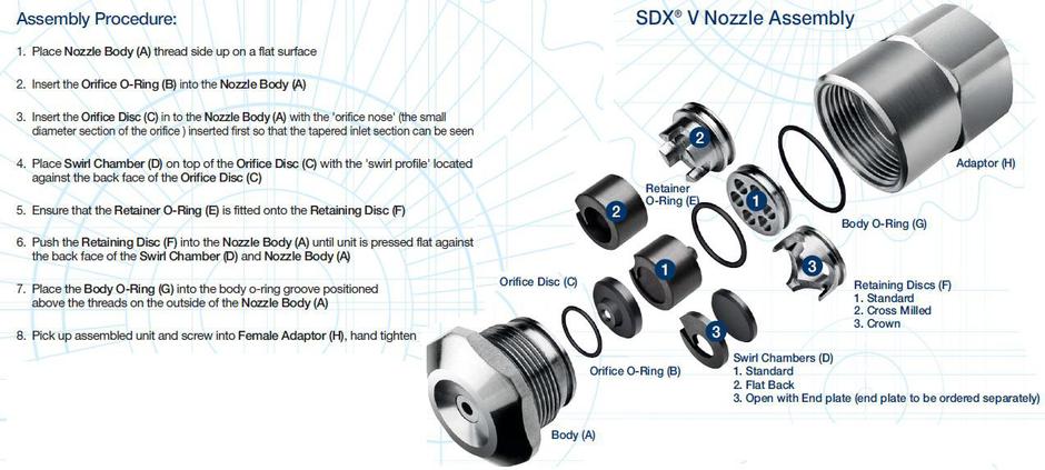
SDX V Assembly Procedure
- Place the nozzle body thread side up on a flat surface
- Insert the orifice seal
- Place the orifice disc inside the nozzle body with the orifice nose i.e. :the smallest diameter first inserted into the body orifice.
- Place the swirl chamber on top of the orifice, with the larger diameter flat surface (swirl end) in contract with the orifice disc.
- Ensure that the retaining disc o’ring is fitted onto the retaining disc.
- Push the retaining disc into the body until the unit pressed against the back face of the swirl chamber. At this point the retaining disc o’ ring will have locked into position with the corresponding groove in the nozzle body.
- Place body seal into body seal groove positioned above the threads on the outside of the body
- Pick up the assembled unit and screw into the female adaptor
- Hand tighten the assembly
CAPACITY CHARTS
Sorry, the comment form is closed at this time.